Background
ECG stands for ElectroCardioGram and is an electronics circuit used to monitor the electrical activity of the heart. The heart pumps due to an electrical wave that is pulsed through it. This circuit can capture those impulses and monitor the function of the heart. During these labs, I explored each stage of the circuit, built it and subsequently used it to pick up live heart impulses.
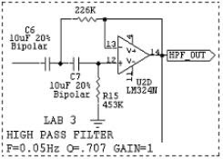
Stage 1 - High Pass Filter
The first stage of the ECG circuit was a high pass filter. The high pass filter was designed to eliminate low frequency noises and have a gain of one. Amplification would come later.
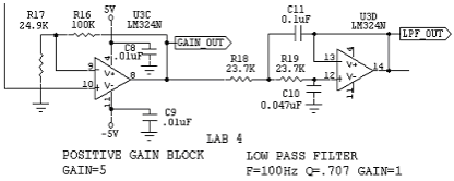
Stage 2 - Active Gain Amplifier and Low Pass Filter
The second stage was a gain amplifier and low pass filter built onto the end of the high pass filter. The active gain amplifier was setup to have a gain of 5, while the low pass filter had a cutoff frequency of 100Hz.
Stage 3 - Notch filter
Next, a notch filter was implemented to eliminate noise from the power supply. The following circuit removes 60Hz signals while allowing others above and below that threshold to pass through.
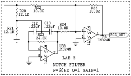
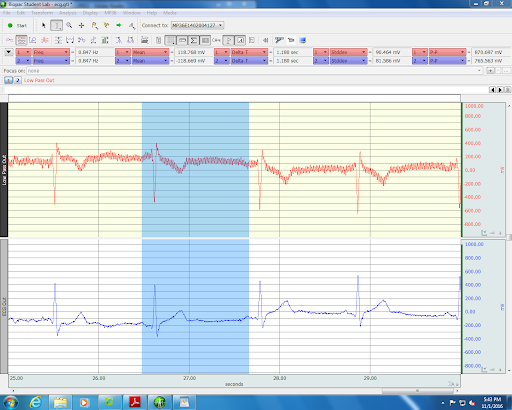
The fast fourier transform of the notch filter response shown on the left in the image below, displays a dip right at 60Hz, corresponding to the elimination of that frequency. Shown on the right in the image below, is the result of this notch filter on the signal. The blue line is much cleaner with less noise impacting the signal.

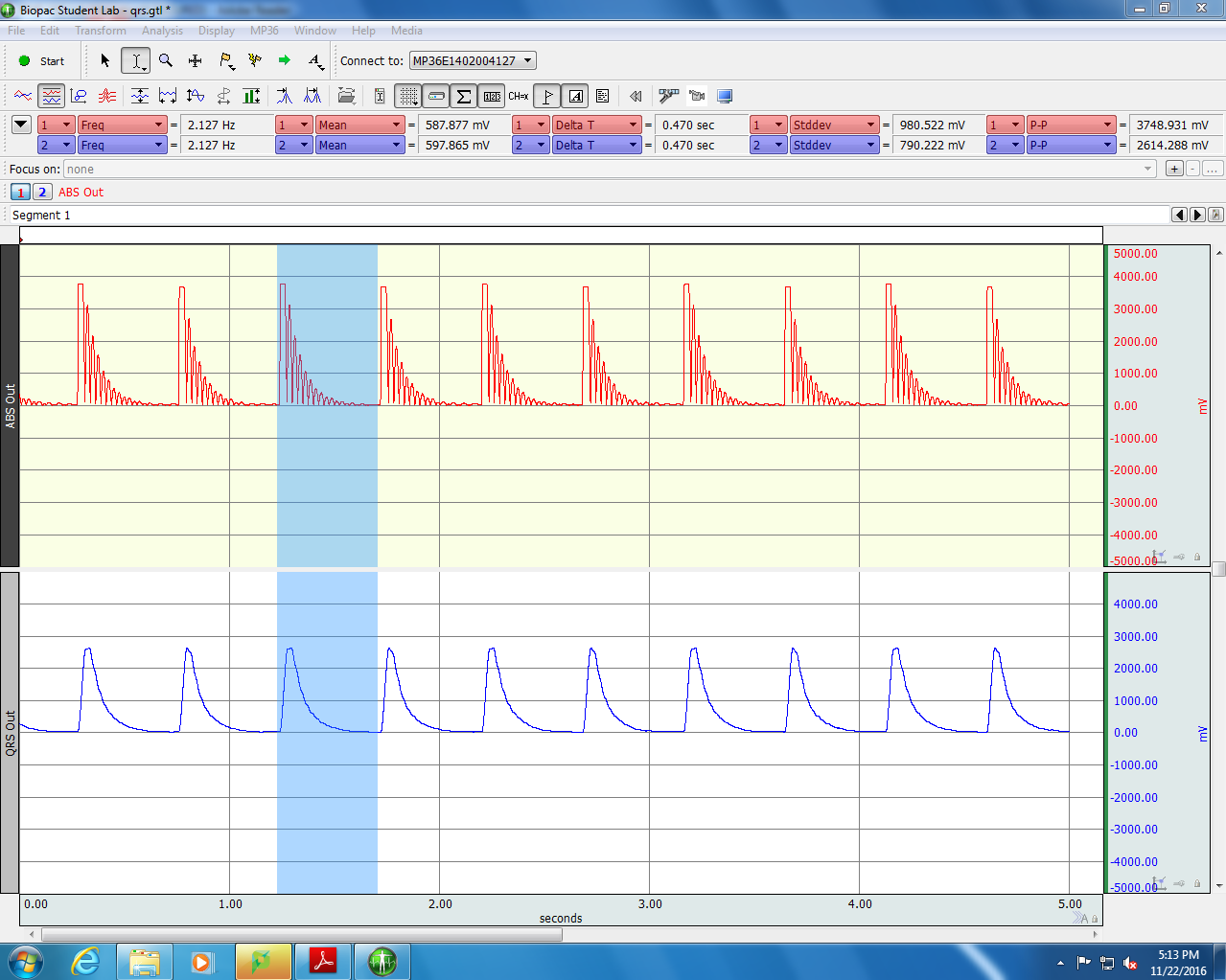
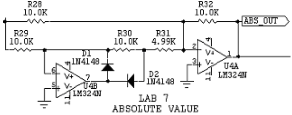
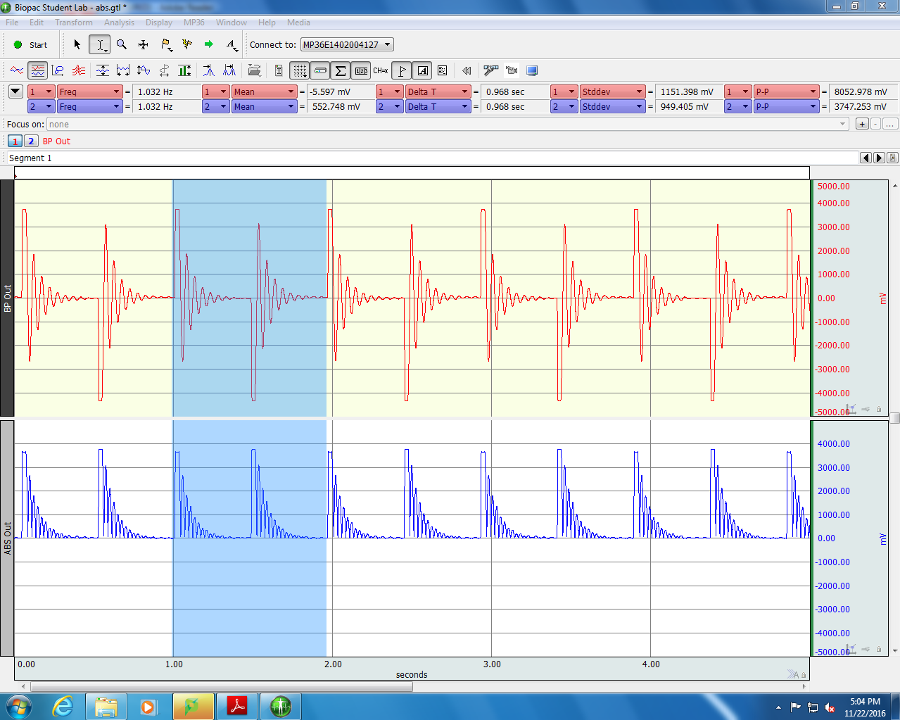
Stage 5 - Absolute Value Circuit
An absolute value circuit was implemented to rectify the waveform and convert it into a DC signal. The result can be seen below on the right, the modified signal, in blue, has had all of its negative elements flipped into the positive domain.
Stage 6 - Another Low Pass Filter
Another low pass filter was connected to the circuit to smooth out the rectified signal. This yielded a smooth signal with a clear peak.