Background
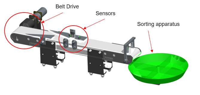
The mechatronics firmware design project was centered around a block sorting system, implemented with an 8-bit AT90USB1289 microcontroller. The microcontroller interfaced with a stepper motor, a DC motor and a plethora of sensors including color, magnetic and laser sensors. The system was used to sort blocks of 4 different materials (black and white plastic, aluminum and iron) into their respective bins (shown in green, in the image below). The goal was to sort the blocks in the fastest time possible with the least amount of errors. My system's best score was 48 pieces in 45 seconds with 1 error. This page summarizes some interesting parts of the project. A video highlighting how the system operated as well as the final design report can be found at the bottom of the page.
Startup
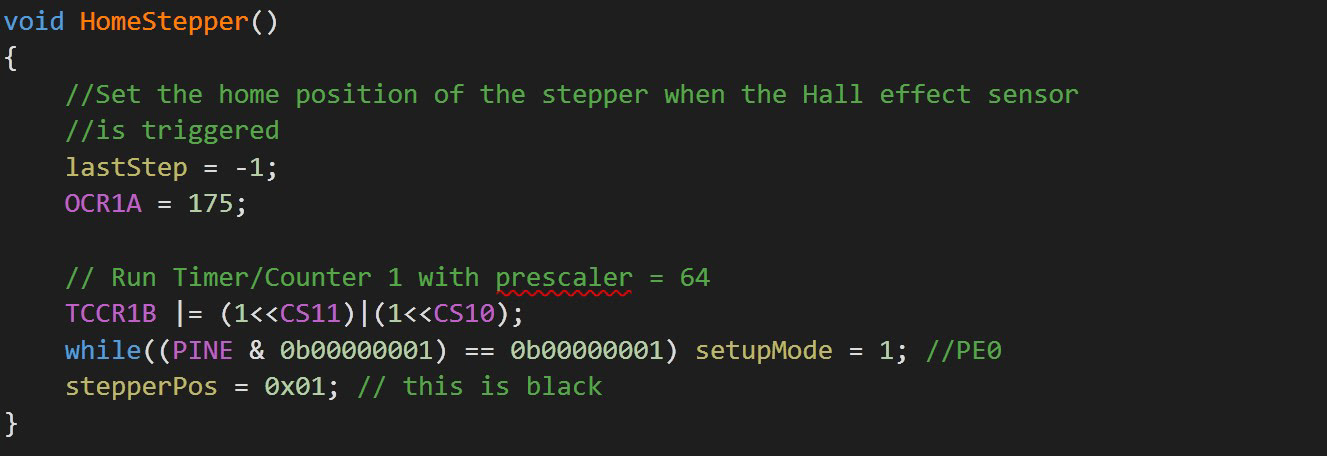
At start up, an important task was positioning the stepper motor correctly so that the bins were oriented correctly for sorting. The stepper motor was run with the use of timer interrupts. Upon startup, the motor was pulsed with one of these timer interrupts. Meanwhile, a second timer interrupt was used to poll the input for the ferromagnetic sensor. Once the ferromagnetic sensor was tripped, the motor was stopped and the variable for the stepper position was saved corresponding to the bin for black plastic parts.
Sensors
Three sensors were implemented in this project: optical reflective, optical interrupt and ferromagnetic sensors. The ferromagnetic sensor was discussed above.
An optical reflective sensor was used to distinguish between the material types based on their color. The optical reflective sensor was paired with an ADC on the controller board and an external interrupt. The interrupt was used to read values from the sensor until the minimum value was found. The code snippet below shows how the part was classified once the lowest value was retrieved.

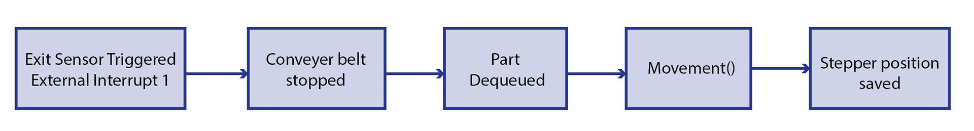
Once the exit sensor was tripped, the physical sorting would take place. The program flow is graphically displayed below. An interrupt would fire, the DC motor would stop the belt and the next part in the linked list would be dequeued. Once dequeued the data from the part would be read and used to position the stepper motor.
Data structure
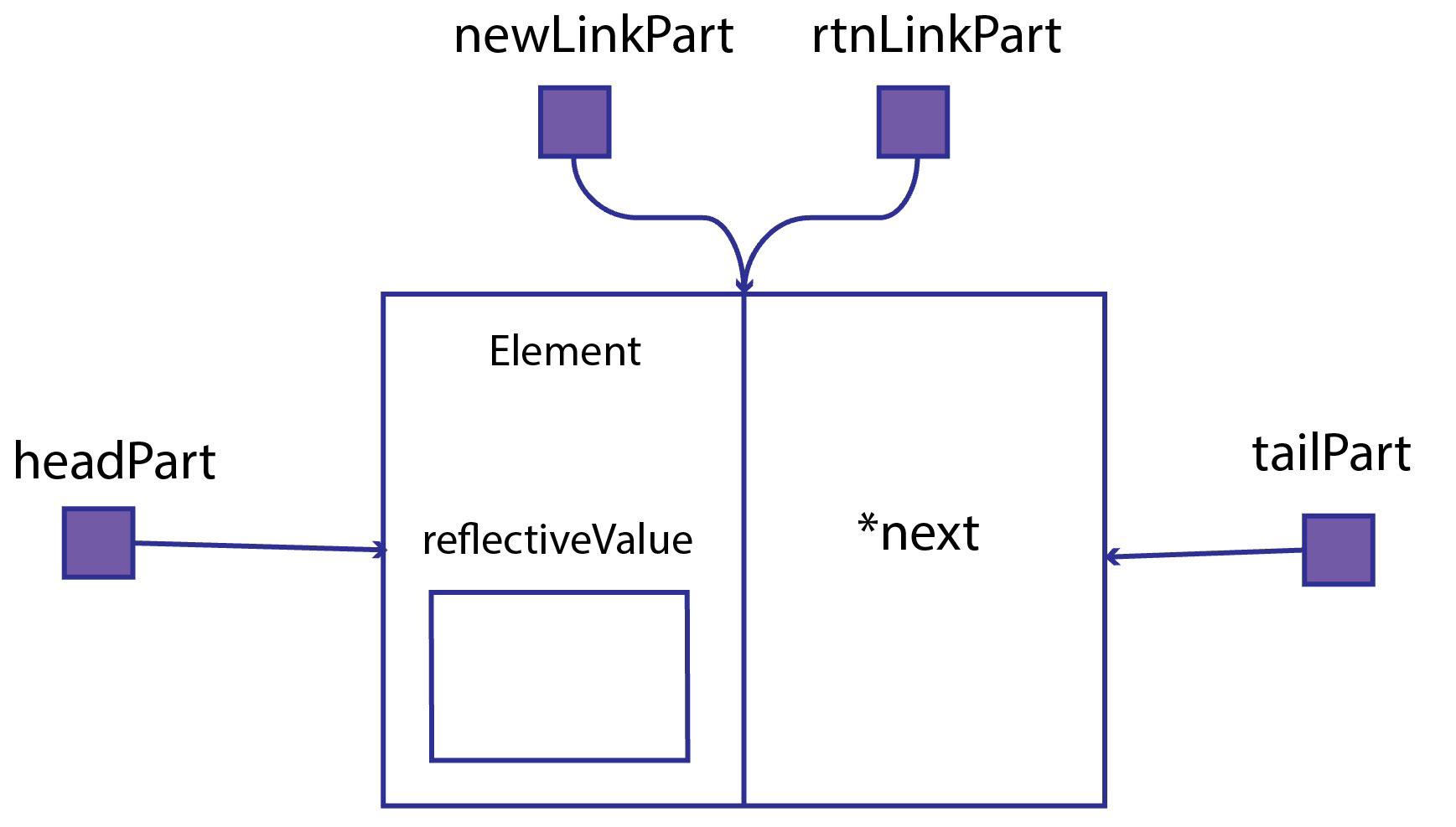
A linked list was used to store data related to the blocks. As each block passed through the optical reflective sensor, data was generated for it and stored in a linked list. Data was added to the head of the list. As a block was sorted by the stepper motor and exit sensor, its data structure was dequeued from the tail of the list. Due to the linear nature and implied first in first out structure of the challenge a linked list was a suitable data structure. Each node in the list had an element for the reflective value obtained from the optical reflective sensor and ADC, as well as pointers to the next and previous nodes in the list.
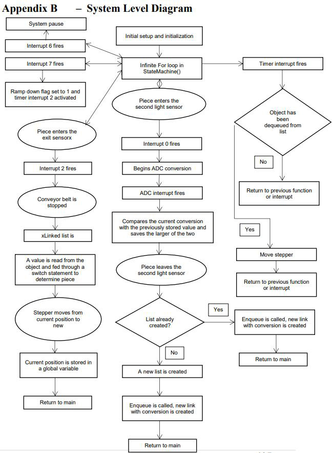
System Level Diagram
The following system level diagram gives an overview of the program flow used to accomplish the sorting challenge.
Result
Improvements
The most important improvement that could have been implemented in the system to decrease sorting time and errors would have been predictive movement of the sorting bins. Every time a piece tripped the exit sensor the belt would stop and the stepper motor would spin to the correct position. A slower but more continuous speed for the belt drive while simultaneously moving the stepper motor would have provided more efficient sorting.
Final Report