Background
At the microscale, fluids have a much stronger tendency towards laminar flow over turbulent flow, due to a small Reynolds number. This poses problems for microfluidics and lab-on-a-chip technologies in which fluids often need to be mixed.
The Challenge
Fully mix fluids dyed blue and yellow in a microfluidic chip that:
- Is no larger than 50mm x 75mm.
- Has a cross-sectional channel size of 300μm x 150μm.
- Operates under continuous flow.
- Has a minimum of 100mm of flow length prior to mixing.
- Has a minimum of 50mm of flow length after mixing.
The Approach
- Conceptual design and analysis.
- Final design and analysis.
Conceptual Designs
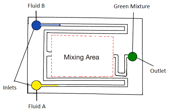
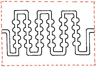
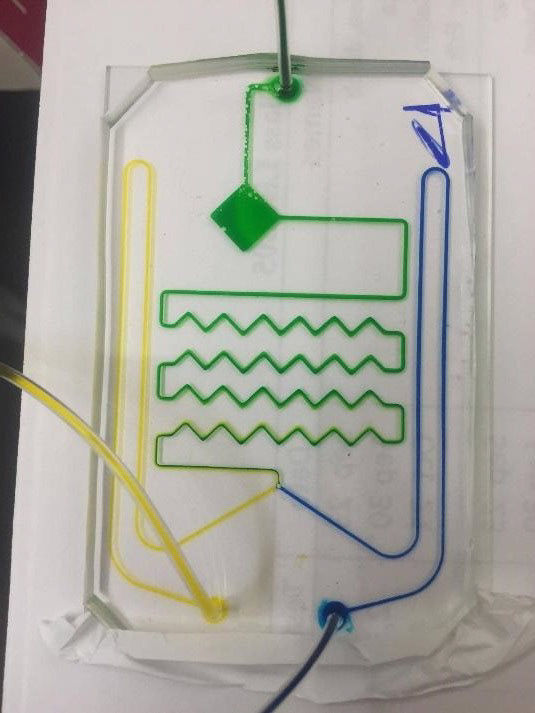
After a literature review of currently used microfluidic mixing technologies, several conceptual designs using different manufacturing methods were created. The peripheral layout remained the same across designs and can be seen in the image below. Two inlets on one end of the chip intake blue and yellow dye before traveling to the other end of the chip and back to meet the pre-mixing length constraint.
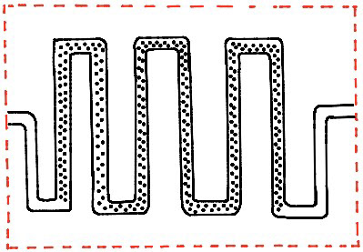
The three mixing area designs are shown in the images below and include a switchback with either zigzags, stationary obstacles or diverging-converging channels.
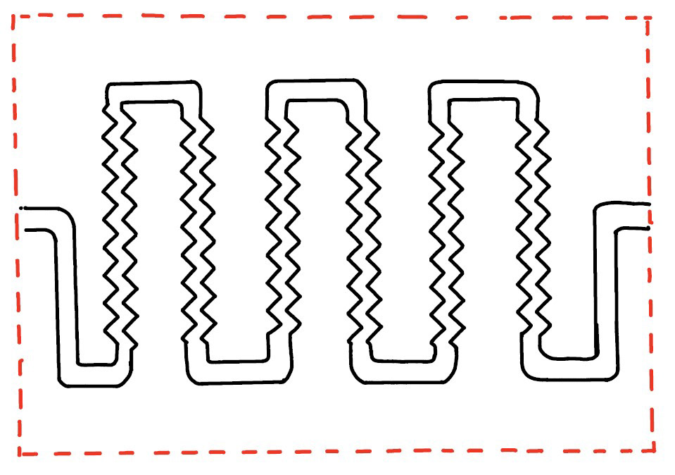
A weighted objectives chart was used to analyze the designs for parameters such as manufacturability, effectiveness of mixing and possibility of leaks. The switchback with zigzags was chosen for the mixing portion of the chip as it was found to have just as good mixing characteristics but would be significantly easier to manufacture.
Prototypes
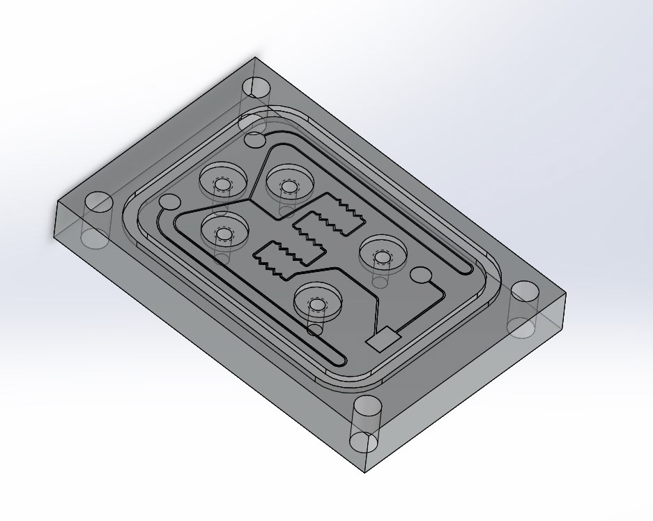
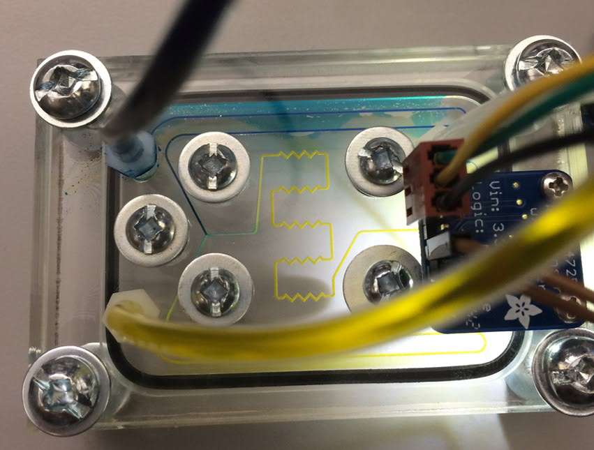
Two manufacturing methods were used for making prototypes. The first was milling the chip outline and an O-ring groove from acrylic before laser cutting the channel pattern into one face of the acrylic and bolting it to another flat piece of acrylic.
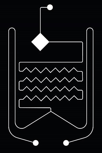
The second more traditional method was photolithography with Polydimethylsiloxane (PDMS). The mask on the left below was used to expose and harden a thin coat of UV-sensitive material, before the rest was chemically removed. The resulting mold was then used to cast the PDMS, before that was bonded to a glass microscope slide.
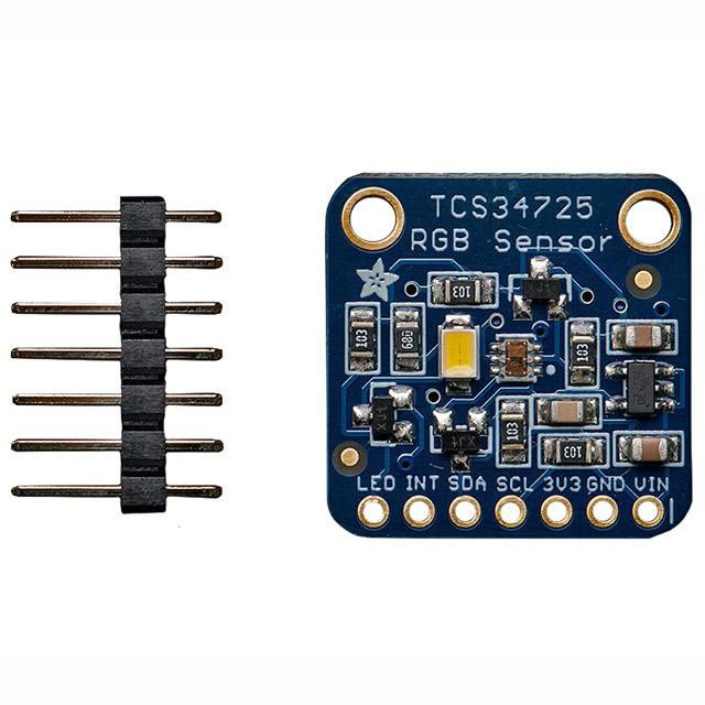
Colour Detection
To confirm proper mixing, a TCS3472 color sensor from Texas Advanced Optoelectronics Solutions was used with an Arduino Leonardo microcontroller.